Topic 6.1 Machining accuracy
6.1.1 Standardization of permissible
deviations of sizes, forms
and placement of surfaces
One of the important
indicators of the quality of the machine, which significantly affects all
criteria of its efficiency and reliability, as well as operational parameters,
is the accuracy of manufacturing and assembly of conjugated elements. The
principle of designing and manufacturing parts, which ensures the possibility
of correct assembly or replacement during repairs of independently manufactured
parts and assembly units without additional processing and fitting them while
maintaining the appropriate quality and reliability of the connection, is
called interchangeability, which is
a characteristic feature of modern mechanical engineering.
A distinction is made
between complete and incomplete interchangeability. Complete - provides for the correct connection of all conjugated
parts entering assembly operations. They are provided with high precision in
the manufacture of parts. In the case of incomplete
interchangeability, the correct connection of only part of the parts
manufactured with lower accuracy is achieved. In these cases, group selection
of parts is used for assembly (selective assembly) or various compensators and
other additional technological means are used.
The
interchangeability of machine parts is ensured by the system of tolerances and
fits. The general provisions and foundations of the construction of this system
for smooth machine elements (cylindrical or limited by parallel planes) with
nominal dimensions up to 3150 mm are established by standards. In accordance
with these standards, we will consider some terminology related to the concepts
of dimensions, deviations, tolerances, and qualities.
Size – numerical value of a linear real value (diameter, length, etc.) in
the selected units. In mechanical engineering, dimensions are given in
millimeters. There are actual, marginal and nominal sizes.
Effective size - the size of the element, which is established
by measurement.
Boundary dimensions
are two maximum allowable dimensions of an element, between which the actual
size must be. The largest (smallest) limit size is the largest (smallest)
allowable element size.
The nominal size is the size relative to
which deviations are determined. The nominal dimensions are selected during the
design process based on strength calculations or on the basis of constructive
considerations and are placed on the drawing of the parts or the connection of
parts.
Deviation is the algebraic difference between the real (or
limit) and the corresponding nominal dimensions.
Limit deviation is the algebraic difference between the
limit and the corresponding nominal dimensions. Distinguish between upper and
lower deviation. The upper (lower) deviation is the algebraic difference
between the largest (smallest) limit and the corresponding nominal dimensions.
The zero line is a line corresponding to
the nominal size, from which size deviations are set aside in the graphic
representation of the fields of tolerances and landings. In the case of
horizontal placement, its positive deviations are placed upwards from it, and
negative deviations are placed downwards.
Tolerance is the difference between the largest and smallest
limit dimensions or the algebraic difference between the upper and lower
deviations. The tolerance field is a field limited by the largest and smallest
limit sizes and is determined by the tolerance and its position relative to the
nominal size.
Tolerance fields for
conjugated elements are set differently for three ranges of changes in nominal
sizes: small - up to 1 mm, medium - 1...500 mm and large - 500...3150 mm. In
mechanical engineering, the average range of nominal sizes is the most widely
used.
The main deviation is one of the two limit
deviations (upper or lower), which determines the position of the tolerance
field relative to the zero line. In the standard tolerance system, there is a
deviation closer to the zero line.
To meet the
requirements for various parts and their fits with certain nominal dimensions,
the standard provides a range of tolerances and basic deviations that
characterize the position of these tolerances relative to the zero line. The
location of the tolerance field in relation to the zero line, which depends on
the nominal size, is indicated by a letter (sometimes two) of the Latin
alphabet, while for holes - a large letter, and for shafts - a small letter.
The greater the size
tolerance, the lower the requirements for the accuracy of the part, the simpler
and cheaper its manufacture. But large parts are more difficult to manufacture
compared to smaller ones with the same deviations from the nominal dimensions.
Therefore, the tolerance is determined by the dimensions of the part. In
addition, the part can be made more precisely (with a smaller tolerance field)
and less precisely (with a larger tolerance field).
To assess the degree
of accuracy, qualities are used -
this is a set of tolerances that corresponds to one level of accuracy for all
nominal sizes. The standard provides for 20 qualities. In order of decreasing
accuracy, qualities are marked as follows: 01,0,1,2,3...18. Qualities
01,0,1,2,3 and 4 are intended for final measures of length, gauges, etc.; in
qualities 5...13, tolerances are given for the dimensions of the mating
surfaces of parts; in qualities 14...18 - for sizes of non-conjugated surfaces.
Since the tolerance
field is determined by the quality, and its position relative to the zero line
is indicated by a letter, the limit deviations of linear dimensions can be
indicated on the drawing of the part by conventional designations of the
tolerance fields. At the same time, the number indicating the size is followed
by the conventional designation of the tolerance field from letters and
numbers, for example, 20H7 or 42с8.
The tolerance field
and limit deviations are given in the tables of the standard and are sometimes
placed in parentheses after the conventional notation of the tolerance field
20H7 (+0.021), 42с8![]() . Deviations equal to zero are not shown in the marking. Two limit
deviations can be positive (in the case when two limit sizes are larger than
the nominal), negative (two limit sizes are smaller than the nominal) and one
positive and the other negative (one limit size is larger and the other is
smaller than the nominal).
. Deviations equal to zero are not shown in the marking. Two limit
deviations can be positive (in the case when two limit sizes are larger than
the nominal), negative (two limit sizes are smaller than the nominal) and one
positive and the other negative (one limit size is larger and the other is
smaller than the nominal).
The accuracy of the part is understood as
its compliance with the requirements of the drawing: in terms of size,
geometric shape, the correct mutual placement of the surfaces being processed
and the degree of their roughness. Regarding the part, there are three
standards of accuracy: accuracy of linear dimensions; accuracy of form;
accuracy of mutual placement of surfaces.
Allowance for linear
dimensions, deviations in form and mutual placement of surfaces affects the
structure of the technological process, labor intensity and cost of products.
The accuracy of parts manufacturing is characterized by deviations from the
given shape and deviations in the mutual placement of individual surfaces. Such
deviations are limited by the appropriate
tolerances assigned under the specific operating conditions of the coupled
parts.
Deviations of the form of conjugated parts
with flat surfaces include non-linearity and non-planarity (Fig. 6.1). Non-linearity is a deviation from a
straight line of the profile of a cross-section of a surface in a plane normal
to it in a given direction. Non-planarity
is a deviation from straightness in any direction along the surface, for
example, convexity, concavity.
Non-planarity surface profile Real Non-linearity
Real straight line An adjacent ![]()
![]()
![]()
![]()
![]()
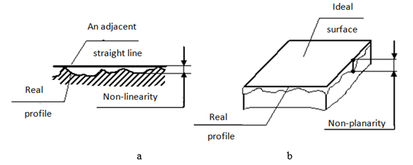
Fig. 6.1 - Deviation of the
shape of parts with a flat surface
Cylindrical surfaces may have deviations in
shape in transverse and longitudinal sections. Thus, in the cross-section,
deviation of the surface contour from a regular circle is possible -
non-circularity, partial types of which are circumference and ovality (Fig.
6.2, a), which are characterized by the dmax-dmin difference. The following
deviations are possible in the longitudinal section of cylindrical surfaces:
barrel-like, curved, saddle-like and conic (Fig. 6.2, b).
Limit deviations of the shape of
cylindrical surfaces are limited by tolerance fields on the diameter of these
surfaces.
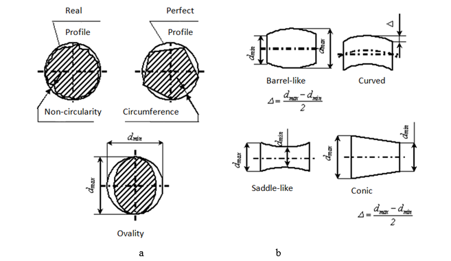
Fig. 6.2 - Deviation
of the shape of parts with cylindrical surfaces:
a – in a cross
section, b – in a longitudinal section
Regarding surface
placement deviations, the following should be noted. The standard provides for
the following deviations in the placement of parts surfaces:
ü for planes – non-parallelism and
non-perpendicularity;
ü for cylindrical surfaces – misalignment,
radial and end runout;
ü for axes - misalignment of axes, deviation
from the correct placement of intersecting axes and passing axes.
Limit
deviations and placement of surfaces are indicated on the drawings. On the
drawings, the sign and numerical value of the deviation are entered in a
rectangular frame divided into two or three parts (Fig. 6.3).
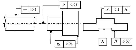
Fig.
6.3 – Designation of the limit deviations of the shape of details on the
drawings
In
the first part (on the left), the tolerance sign is indicated, in the second -
the numerical value of the limit deviation (in mm), and in the third - the
letter designation of the base or other surface. Bases are indicated by a
shaded equilateral triangle or a capital letter. The direction of the line
segment with the arrow must correspond to the direction of the deviation
measurement.
6.1.2 Methods of achieving processing accuracy
The
accuracy of processing on the machine is determined by the following factors:
1.
Quality of manufacturing and condition of machines and tools.
2.
Accuracy of tool installation.
3.
Deformation of the technological system.
4.
Inconsistency of the allowance on the surface of the part and inconstant
hardness.
5.
Temperature deformation in the technological system during the cutting process.
6.
Wear of the cutting tool.
7.
Deformation of the workpiece from the cutting force.
8.
Deformation of the workpiece as a result of stress redistribution during
removal of the allowance
9.
Qualification and discipline of the worker.
10.
Measurement error.
The
given accuracy of workpiece processing can be achieved using two fundamentally
different methods: trial runs and measurements; by the method of automatically
obtaining dimensions on adjusted machines.
The method of trial passages and
measurements
The
essence of the method is that a cutting tool is brought to the machining
surface of the workpiece mounted on the machine and a test chip is removed from
a short section of the workpiece. After that, the machine is stopped, a trial
measurement of the obtained size is made, the amount of its deviation from the
one indicated on the drawing is determined, and a correction is made to the
position of the tool, which is calculated by divisions of the limb of the
machine. Then, a trial processing ("stroke") of the workpiece section
is again carried out, a new trial measurement of the obtained size is made and,
if necessary, a new correction is made to the position of the tool. Thus, by
trial runs and measurements, the correct position of the tool relative to the
workpiece is established, which ensures the required size. After that, the
workpiece is processed along its entire length. When processing the next
workpiece, the entire tool installation procedure is repeated with trial
passages and measurements.
Marking
is often used in the method of trial passages and measurements. In this case,
thin lines are drawn on the surface of the workpiece with special tools
(drafting machines, rod-reamers, etc.), which show the outline of the future
part. During the subsequent processing, the worker tries to combine the
trajectory of the cutting blade of the tool with the line of marking the
workpiece and thereby ensure that the given shape of the processed surface is
obtained.
Advantages of the method: high accuracy of processing is
obtained on imprecise equipment; when processing a batch of small blanks, the
influence of the wear of the cutting tool on the accuracy of the dimensions
maintained during processing is excluded; in case of inaccurate preparation, it
allows you to correctly distribute the allowance and prevent the appearance of
defects; frees the worker from the need to manufacture a complex and expensive
device.
Disadvantages of the method: the dependence of processing accuracy
on the minimum thickness of the chip to be removed; the appearance of a defect
due to the fault of the worker; low productivity of processing, due to the
large amount of time spent on trial passages, measurements and marking; high
cost of processing the part due to low productivity in combination with high
qualification of the worker.
As a
result, this method is used in
single or small-batch production, research production, as well as in repair and
tool shops. In multi-series and mass grinding, because it allows compensating
for the wear of the abrasive tool.
The method of automatically obtaining
dimensions on adjusted machines
When
processing workpieces using this method, the machine is pre-adjusted in such a
way that the accuracy required from the workpiece is achieved automatically,
that is, almost regardless of the qualification and attention of the worker.
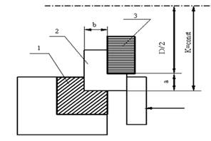
For example, when milling workpiece 2
to dimensions a and b, the table of the milling machine is
pre-set in height so that the support surface of the stationary jaw 1 of the vice is to the axis of rotation
of the milling cutter at a distance of K=D/2+a
(Fig. 6.4). At the same time, the side surface of the milling cutter 3 is moved away from the vertical
surface of the stationary sponge by a distance b.
|
Fig. 6.4 |
This preliminary adjustment of the
machine is carried out by the method of trial passages and measurements.
After such adjustment, the entire batch of blanks is processed without their
intermediates and without additional movements of the machine table in the
transverse and vertical directions. Just as in the process of processing, the
dimensions K and b remain unchanged, |
so the accuracy of the dimensions a and b remains the same for all workpieces processed on the machine with
this setup.
Advantages of the
method:
increasing the accuracy of processing and reducing defects; growth of labor
productivity; rational use of highly qualified workers; increasing production
efficiency.
The
method of automatically obtaining dimensions on adjusted machines is to a large
extent devoid of the disadvantages
inherent in the method of trial passages and measurements. With this
method, the task of ensuring processing accuracy is transferred from the
worker-operator to the adjuster, toolmaker and technologist.
The
method is widely used in modern
serial and mass production.
Each
of the considered methods of achieving the specified accuracy is definitely
accompanied by processing errors caused by various reasons of a systematic and
random nature. Accordingly, errors arising from these causes are divided into
systematic and random.