Laboratory lesson №2
Topic: Production and technological
process. The structure of the technological operation
Objective of the work - design of the technological process of
machining a stepped shaft; familiarization with the control system of the
machining process on a lathe.
Equipment, tools and materials:
1.
Working drawings of the part.
2. The lathe.
3.
Technological process of machining by transitions.
4.
Cutting tools: undercutting, boring, grooving and cutting lathe cutters.
5.
Measuring tools: caliper 0-175 (p/d = 0.01 mm), micrometer
0-50 (p/d = 0.01 mm).
6.
Reference books and tutorials.
Theoretical information
The development of the
process is carried out in a simplified form for one operation by transitions.
After selecting the workpiece,
the method of its fixture is determined, all transitions are outlined,
indicating the diameter of the machining and the actual length of each
transition, and the tool is selected. For example, for the part shown in Fig.
2.1, the technical process is presented in Table 2.1. The workpiece is mounted in a
three-jaw chuck according to its outer diameter.
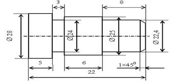
Fig. 2.1 -
Drawing of the stepped shaft
Table 2.1
|
Transitions |
Contents of transitions |
Tool |
|
1 |
To
sharpen Æ25 in size 22 mm |
№1 passable |
|
2 |
To
sharpen Æ28 in size 12 mm |
№1 passable |
|
3 |
Chamfering
1×450 |
№1 passable |
|
4 |
To
sharpen Æ22,4 in size 8 mm |
№2 passable |
|
5 |
To
sharpen a groove 3 mm, Æ 24 mm |
№3 grooving |
|
6 |
Сut away in size 22 mm |
№4 cutting |
Draw a setup sketch as
shown in Fig. 2.2. The sketch must repeat the operational sketch of the part,
show the overhang of the workpiece
and chuck and the amount of longitudinal movement of the slide.
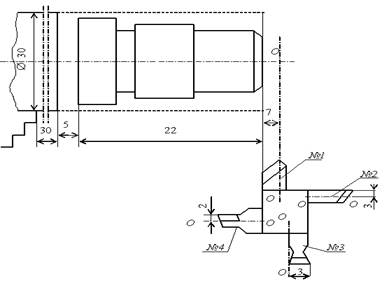
Fig. 2.2 - Setup diagram
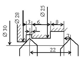
Development of a machine tool slide motion pattern (Fig. 2.3). The
length of the transverse and longitudinal feed paths of the caliper
is plotted on the diagram: for the transverse feed, the initial and final
diameters, and for the longitudinal feed, the distance travelled.

Fig. 2.3 - Schematic diagram of the caliper
movement
For the example under
consideration, the movements will be as follows: transverse feed of the slide
for turning Ø25
mm; longitudinal feed of the slide to a length of 22 mm (Fig. 2.4, a); withdrawal
of the slide in the transverse direction and its re-entry for turning Ø28
mm to the working length of the slide feed to a length of 12 mm (Fig. 2.4, b);
then withdrawal of the slide in the transverse direction by 2 mm and return in
the longitudinal direction to the starting position. The length of the
transverse and longitudinal feed paths of the caliper
is plotted on the diagram: for the transverse feed, the initial and final
diameters, and for the longitudinal feed, the distance travelled.
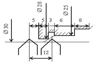
a
b
Fig. 2.4 - Diagram of the tool position and end of the
machining pass:
a - Ø25
mm, b - Ø28
mm
The procedure for performing the work
1. Development
of the technological process of the operation by transitions.
2. Sketch
of the workpiece
and setup.
3. Drawing
up a diagram of the caliper movement.
4. Setting
the cutting modes.
5. Performing
work and checking the dimensions obtained in accordance with the task.
Contents of the work report
1. Title
of the work.
2. Purpose
of the work.
3. Name
of the machine, model, technical characteristics.
4.
Cutting tool, material.
5. Data
on measuring instruments: name, price of division.
6. Cutting
modes.
7. Sketch
of the workpiece
and parts, material.
8. Technological
process of machining a part in one operation by transitions.
9. Scheme
of adjustment.
10.
The scheme of movement of the caliper.
11.
Conclusions.
![]()
![]()